


 Forget your password?
 SIGNUP
 LOGIN
LOGIN
Concrete Detailing Workflow: From Design to Construction Drawings
Quick Answer
A concrete detailing workflow is the controlled process of turning approved structural design information into coordinated reinforcement drawings, bar bending schedules (BBS), cut-off tables, quantity information, and editable CAD deliverables for construction.
It begins with verified design inputs and ends with issue-ready documentation. The workflow supports the structural engineer by improving clarity, coordination, and review efficiency; it does not replace engineering judgment or final technical responsibility.
What Is a Concrete Detailing Workflow?
Concrete detailing is not a single drafting task. It is a sequence of engineering and documentation activities that must remain connected from the first review of design information to the final issue of construction drawings.
A reliable workflow answers practical questions before the work reaches the site: which bars are required, where they start and stop, how they are anchored or spliced, how they are identified on drawings, and how the same information is reflected in schedules.
For a broader explanation of the tools involved, see our guide to concrete detailing software. This article focuses on the workflow itself: the steps that turn design information into coordinated construction documentation.
Why a Structured Detailing Workflow Matters
Structural design and construction documentation are related, but they serve different purposes. Design verifies that members can meet strength, serviceability, ductility, and code requirements. Detailing communicates how those members should be reinforced, fabricated, checked, and built.
When the workflow is incomplete or poorly coordinated, issues often appear late in the project, when changes are harder and more expensive to make. Common risks include:
- Reinforcement congestion at beam-column joints and critical zones
- Bar marks that do not match between drawings and schedules
- Missing or unclear splice, anchorage, hook, and development information
- Conflicting beam, column, section, and plan views
- Unclear continuity of reinforcement between floors
- Incomplete cut-off information that increases avoidable steel waste
- Revisions that are not reflected consistently across the drawing package
A structured workflow gives the engineer defined review points before documents are issued for fabrication or construction.
Stage 1: Confirm the Design Basis
The workflow should begin only after the engineer has confirmed the design basis for the package being detailed. Detailing from incomplete or unverified information creates rework later, even when the drawing quality is high.
Before starting, confirm:
- Structural system and member layout
- Grid lines, levels, dimensions, and member cross-sections
- Material grades and reinforcement bar sizes
- Governing design code and project-specific specifications
- Required ductility level and seismic detailing rules, where applicable
- Design reinforcement requirements and any engineer-approved revisions
- Drawing standards, units, sheet sizes, scales, and naming conventions
This stage establishes a single source of truth for the detailing package. Changes to the design basis should be controlled and communicated before they are incorporated into drawings or schedules.
Stage 2: Establish the Model and Project Setup
Once the design basis is confirmed, the structural model and project settings must be organized for execution-level review. The objective is not simply to view members in three dimensions; it is to understand their relationships before individual drawings are prepared.
At this stage, engineers typically review grids, floors, beam and column locations, member elevations, section dimensions, and geometric relationships. Project settings should also be established for units, reinforcement sizes, cover, drawing scales, layers, and sheet organization.
A model-based review is particularly useful for identifying geometry or coordination issues that may be difficult to notice in isolated plan views. It also helps the project team maintain consistent references between floors, elevations, and individual member details.
Stage 3: Define Detailing Rules and Code Controls
Reinforcement cannot be detailed correctly without clear detailing rules. Before bars are arranged, the project team should establish the requirements that control how those bars are shown, spaced, anchored, and scheduled.
Typical controls include:
- Concrete cover requirements
- Available reinforcement diameters and bar marks
- Development lengths, hooks, bends, and anchorage details
- Lap splice locations and lengths
- Mechanical splice or coupler requirements, where used
- Stirrup and tie spacing rules
- Critical zone and confinement requirements
- Minimum and maximum reinforcement spacing limits
- Drawing labels, schedule formats, and rounding rules
These controls should be checked against the governing code and project specifications. A consistent rule set reduces the risk of applying different assumptions to similar members across the same project.
Stage 4: Detail Columns First
Columns are often a logical starting point because their reinforcement affects continuity across floors, connections to foundations, and congestion at beam-column joints. Column detailing should make the vertical load path and reinforcement arrangement clear from one level to the next.
A complete column detailing review may include:
- Longitudinal bar quantity, size, and arrangement
- Tie configuration and spacing
- Critical length and confinement zones
- Lap splice locations and splice lengths
- Mechanical splices or couplers, where required
- Starter bars and footing connection information
- Column alignment, rotation, and inclined-column conditions
- Reinforcement continuity through repeated floors
Before moving to beams, the engineer should confirm that column details are practical to fabricate and place, especially in heavily loaded or highly reinforced members.
Stage 5: Detail Beams and Beam-Column Joints
Beam detailing defines how reinforcement is distributed along the member and how that reinforcement is coordinated at supports, joints, changes in section, and adjacent spans. This stage requires careful attention because congestion can develop quickly where beams frame into heavily reinforced columns.
Beam detailing typically addresses:
- Top and bottom longitudinal reinforcement
- Stirrups, shear reinforcement, and torsional reinforcement where required
- Bar spacing, cover, and clear placement requirements
- Splice and cut-off locations
- Beam elevations, cross-sections, and support conditions
- Changes in beam width or depth
- Mechanical splices, where specified
- Beam-column joint information and constructability review
The goal is not only to satisfy calculated reinforcement requirements. The finished detail must also communicate a practical arrangement that can be read, checked, fabricated, and placed on site.
Stage 6: Build Schedules, Cut-Off Tables, and Quantity Information
Drawings and schedules must be produced as one coordinated package. A drawing can show where a bar belongs, while a bar bending schedule provides the fabrication and control information needed to cut, bend, deliver, and verify that bar.
A coordinated BBS normally identifies the bar mark, diameter, shape, length, quantity, weight, and member or floor reference. Reinforcement cut-off tables then clarify where bars begin, terminate, continue, or change within beams and columns.
Quantity information should be reviewed alongside the drawings and schedules, not after them. This helps the team identify unexpected quantities, duplicated bars, inconsistent marks, or avoidable waste before fabrication starts.
Stage 7: Review, Coordinate, and Issue Deliverables
The final review is where the workflow becomes a construction package. Before issue, the engineer should verify that the drawings, schedules, and supporting information describe the same reinforcement arrangement.
Use this final checklist:
- Member names, references, and floor labels are consistent
- Bar marks match between drawings, BBS tables, and cut-off tables
- Dimensions, cover, spacing, and section references are readable
- Splice, anchorage, hook, bend, and coupler details are complete
- Beam-column joints and congested areas have been reviewed
- Reinforcement continuity between floors is clear
- Drawing revisions are identified and coordinated
- Sheet scales, title blocks, and output formats meet project requirements
The final deliverables may include beam drawings, column drawings, reinforcement layout plans, BBS reports, cut-off tables, quantity or wastage information, and editable CAD files.
What a Construction-Ready Detailing Package Should Include
A construction-ready reinforced concrete package should allow site and fabrication teams to understand the required work without relying on assumptions. Depending on the project, it may include:
- Detailed beam and column drawings
- Reinforcement layout plans
- Member elevations and cross-sections
- Bar bending schedules for the project, floor, or member group
- Reinforcement cut-off tables
- Steel quantity and wastage information
- Clearly identified revisions and issue status
- Editable DWG or DXF drawing files for coordination
Clarity matters as much as completeness. A technically correct drawing that cannot be read efficiently in the field can still create delays and mistakes.
How SIDA Concrete Supports the Concrete Detailing Workflow
SIDA Concrete supports a model-based reinforced concrete drafting and verification workflow in a 3D environment. It enables engineers to review execution-level structural components, work with grids, materials, reinforcement bar sizes, and project units, then prepare coordinated beam and column documentation.
For workflow control, SIDA Concrete provides ACI-based settings, reinforcement development and bend-extension controls, and ductility settings for Special and Intermediate Moment Resisting Frames. Its column tools support items such as splice length and location, starter bars, critical zones, high axial-force checks, inclined columns, mechanical splices, and reinforcement continuity across multiple floors.
For beams, the workflow can include inclined-beam drafting, reinforcement merging across varying beam dimensions, beam typification, beam elevation alignment, mechanical splices, beam-column joint shear checks with calculation reporting, spacing controls, torsional reinforcement distribution, and code-compliance notifications.
At the output stage, SIDA Concrete can generate detailed beam and column drawings, reinforcement layout plans, AutoCAD block-based drawings, project-wide and member-level BBS reports, cut-off tables, steel wastage reports, floor-based drawing outputs, and DWG/DXF exports.
Build a More Controlled Concrete Detailing Workflow
SIDA Concrete helps structural teams organize beam and column detailing in a model-based 3D environment, then prepare coordinated reinforcement drawings, bar bending schedules, cut-off tables, quantity reports, and editable DWG/DXF outputs.
Want a guided product walkthrough? Use the Request Demo form on the SIDA website and select SIDA Concrete.
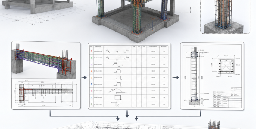
Example Workflow: A Multi-Story Reinforced Concrete Frame
Consider a multi-story building with repeated beam and column types. The engineer first verifies the design basis, grids, floors, member sizes, reinforcement requirements, and project rules. The team then reviews the structural layout in context and establishes the detailing settings that will be used consistently across the project.
Columns are detailed first, including longitudinal bars, ties, critical zones, splice locations, and floor-to-floor continuity. Beams are then detailed with longitudinal reinforcement, stirrups, torsional reinforcement where required, spacing checks, elevations, sections, and beam-column joint information.
After the member details are reviewed, the package is coordinated with BBS reports, cut-off tables, quantity information, and drawing sheets. The engineer then performs the final constructability and revision checks before issuing editable CAD documentation for coordination and construction.
Common Workflow Failures to Avoid
Starting from Unverified Design Information
Detailing should not begin until the structural system, member sizes, reinforcement requirements, and code basis are confirmed. Otherwise, drawings and schedules may need extensive rework after design changes.
Creating Schedules Separately from Drawings
When bar schedules are produced independently of the drawings, mismatches in marks, quantities, lengths, and references become more likely. Treat drawings, BBS data, and cut-off tables as one coordinated deliverable.
Reviewing Congestion Too Late
Plan views alone may not reveal conflicts at beam-column joints, critical zones, or heavily reinforced members. Review the geometry and cross-sections before drawings are issued.
Treating Automated Output as Final
Software can improve speed and consistency, but it cannot replace engineering judgment. Final drawings must be reviewed by a qualified engineer against the governing code, project specifications, and constructability requirements.
Weak Revision Control
Every revision should be reflected consistently in drawings, schedules, cut-off tables, and issue records. A revision that appears in only one part of the package can cause fabrication errors and site delays.
Frequently Asked Questions
What is the correct sequence for concrete detailing?
A reliable sequence is: confirm the design basis, organize the model and project settings, define detailing rules, detail columns, detail beams, build schedules and cut-off tables, then review and issue the coordinated package.
When should a bar bending schedule be prepared?
A BBS should be prepared as part of the detailing workflow while drawings are being coordinated. It should not be treated as a separate document created after the reinforcement drawings are complete.
Does a concrete detailing workflow replace structural design?
No. Structural design establishes the required performance and reinforcement demand. The detailing workflow turns approved design information into practical documentation for fabrication and construction.
What should be checked before issuing reinforcement drawings?
Check member references, bar marks, dimensions, cover, spacing, splice and anchorage details, reinforcement continuity, BBS coordination, cut-off information, revisions, sheet scales, and constructability at congested locations.
Can SIDA Concrete produce CAD-ready drawings?
Yes. SIDA Concrete supports detailed drawing outputs and exports in DWG and DXF formats for AutoCAD-based coordination workflows.
Final Thoughts
A concrete detailing workflow connects structural design intent with construction execution. When each stage is controlled, the final package becomes clearer, more coordinated, and easier to review before materials reach the site.
Want to see how SIDA Concrete fits your engineering workflow? Use the Request Demo form on the SIDA website and select SIDA Concrete for a product walkthrough.
 Write a comment


