


 Forget your password?
 SIGNUP
 LOGIN
LOGIN
What Is Concrete Detailing Software? Complete Guide to Drawings & CAD Output
Quick Answer
Concrete detailing software is a specialized engineering tool used to prepare reinforcement details for reinforced concrete structures. It helps engineers create beam and column drawings, reinforcement layouts, bar bending schedules, cut-off tables, steel quantity information, and editable CAD outputs.It does not replace the structural engineer. Instead, it reduces repetitive drafting work and gives engineers a clearer way to review, organize, and issue reinforcement information for construction.
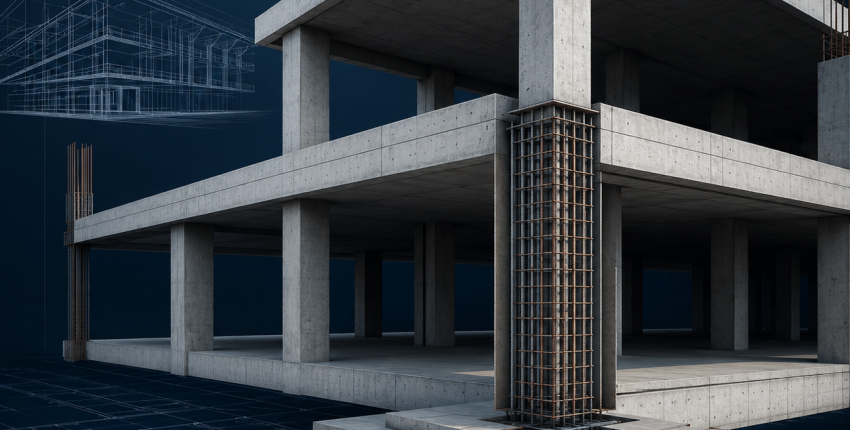
A structural model can show that a beam or column is strong enough. But before that member can be built, the project team still needs practical answers: Which bars are used? Where do they start and stop? How are they spliced, bent, labeled, scheduled, and shown on drawings?
That is the purpose of concrete detailing.
This guide explains what concrete detailing software does, how it fits into a reinforced concrete workflow, what outputs it produces, and how SIDA Concrete supports beam and column detailing in a coordinated 3D environment.
Why Concrete Detailing Matters
Structural design and construction execution are connected, but they are not the same activity.The design stage establishes whether structural members can safely resist the required loads. The detailing stage turns that engineering intent into instructions that fabricators, site engineers, bar benders, and construction crews can understand and use.
Even a well-designed structure can face construction problems when the detailing is unclear or incomplete. Typical issues include:
- Reinforcement congestion at beam-column joints
- Inconsistent bar marks between drawings and schedules
- Missing splice, hook, or development details
- Conflicting revisions between sheets
- Unclear beam and column cross-sections
- Difficulties in reviewing reinforcement continuity between floors
- Excess steel waste caused by incomplete cut-off information
Concrete Design vs. Concrete Detailing
Concrete design and concrete detailing are closely related, but they solve different problems.Concrete Design
Concrete design focuses on structural performance.The engineer checks loads, strength, serviceability, member dimensions, reinforcement demand, ductility requirements, and code compliance.
The main question is:
Can this member safely carry the required loads?
Concrete Detailing
Concrete detailing focuses on constructability and documentation.The engineer defines how reinforcement should be arranged, anchored, spliced, labeled, scheduled, and represented on drawings.
The main question is:
How should this member be built correctly on site?
A complete reinforced concrete project needs both. A safe design still requires practical, coordinated, and readable reinforcement drawings before construction begins.What Does Concrete Detailing Software Produce?
The exact deliverables vary by project and software, but a professional concrete detailing workflow typically produces the following outputs.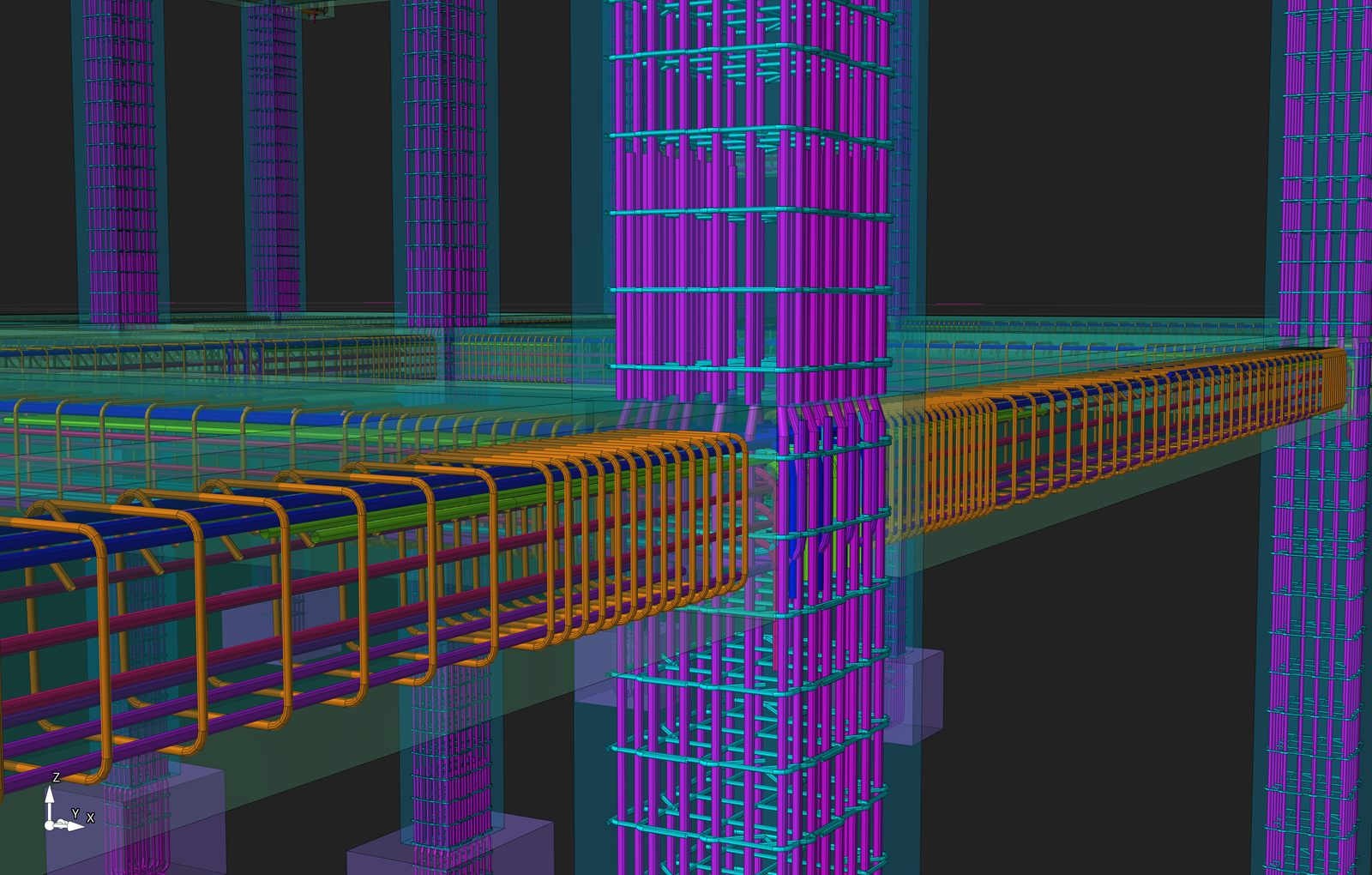
Reinforcement Drawings
Reinforcement drawings show the location, spacing, quantity, shape, and arrangement of bars within structural members.For beams and columns, these drawings may include:
- Longitudinal reinforcement
- Stirrups and ties
- Confinement reinforcement
- Lap splices and mechanical couplers
- Starter bars and dowels
- Cover requirements
- Beam elevations
- Column elevations
- Cross-sections and connection details
Bar Bending Schedules
A bar bending schedule, often called a BBS, organizes reinforcement information for fabrication, cutting, bending, procurement, and site control.A useful BBS usually includes:
- Bar mark
- Bar diameter
- Bar shape
- Length
- Quantity
- Weight
- Member or floor reference
Reinforcement Cut-Off Tables
Cut-off tables clarify where reinforcement begins, terminates, continues, or changes within structural members.They are especially useful on repetitive multi-story projects, where beam and column details must remain consistent across several floors.
Steel Quantity and Wastage Information
A clear detailing workflow can help project teams understand reinforcement quantities and identify avoidable waste before materials are cut and delivered to site.Editable CAD Drawings
DWG and DXF outputs remain important in structural engineering because they allow drawings to be reviewed, coordinated, revised, and integrated with wider project documentation.How Does a Concrete Detailing Workflow Work?
Structural Design Data → SIDA Concrete 3D Model → Beam & Column Detailing → Review → DWG/DXF Output
A reliable workflow usually follows six stages.
1. Confirm the Design Basis
Before detailing starts, the engineer confirms the structural system, member geometry, reinforcement requirements, material properties, governing code, and project-specific rules.This is the engineering foundation of every drawing that follows.
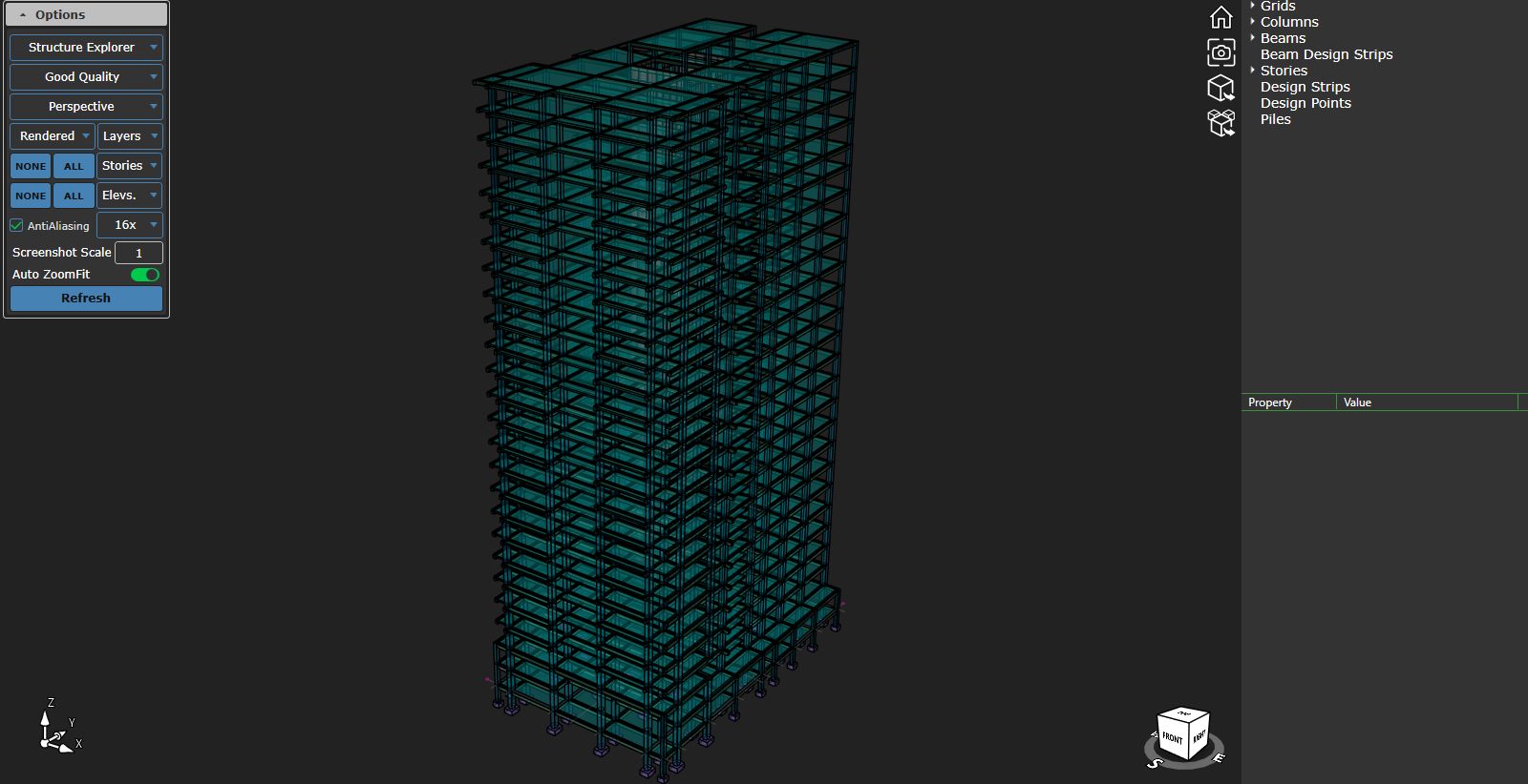
2. Review the Execution-Level Model
Structural members are organized in a model-based environment so engineers can review grids, levels, beams, columns, sections, and reinforcement relationships in context.A 3D environment is valuable because many coordination issues are difficult to identify in separate 2D views.
3. Apply Project and Code Settings
The detailing process applies the project’s preferred rules for cover, bar sizes, development details, splice locations, tie spacing, hooks, bends, and other reinforcement requirements.These settings must always be checked against the governing code and project specifications.
4. Detail Columns
Column detailing may include longitudinal bars, ties, critical zones, splice lengths, starter bars, mechanical splices, footing connections, inclined columns, and reinforcement continuity between floors.The goal is not only to satisfy code requirements but also to make the reinforcement practical to fabricate and place.
5. Detail Beams
Beam detailing may include top and bottom longitudinal bars, stirrups, torsional reinforcement, splice locations, bar spacing, beam elevations, cross-sections, and beam-column joint information.This stage requires careful review because reinforcement congestion can develop quickly at supports, joints, and heavily loaded regions.
6. Review and Issue Deliverables
Before issuing drawings, engineers should review constructability, bar marks, member references, spacing, cover, splice locations, schedules, and revision status.The final package can include detailed drawings, reinforcement plans, BBS tables, cut-off tables, steel quantity reports, and editable CAD files.
What Makes a Reinforcement Drawing Construction-Ready?
A construction-ready drawing should do more than look clean.It should allow a project team to understand exactly what must be built without relying on assumptions.
A strong reinforcement drawing should provide:
- Clear member identification
- Consistent bar marks
- Readable dimensions and spacing
- Complete section references
- Practical splice and anchorage information
- Correct reinforcement continuity
- Coordinated BBS data
- Revision clarity
- Information that can be checked in the field
How SIDA Concrete Supports Reinforced Concrete Detailing
SIDA Concrete is a model-based reinforced concrete drafting and verification solution built around a 3D working environment.It allows engineers to visualize structural components at execution level, review element properties, adjust grids and material settings, define reinforcement bar sizes, and work with user-selected units.
For reinforced concrete detailing, SIDA Concrete provides ACI-based design settings and allows engineers to manage reinforcement development details, including development length and bend extension. It also supports structural ductility settings for Special and Intermediate Moment Resisting Frames.
Column Detailing Capabilities
For columns, SIDA Concrete supports detailing controls for splice length and location, critical column length, starter bars, high axial-force checks, column alignment, inclined columns, coupling and forging splices, tie reinforcement in critical zones, and reinforcement continuity across multiple floors.The software also provides code-compliance notifications to help users identify and correct detailing issues during the workflow.
Beam Detailing Capabilities
For beams, SIDA Concrete supports inclined beam drafting, reinforcement merging across varying beam dimensions, beam typification, beam elevation alignment, mechanical splices, beam-column joint shear checks with calculation reporting, cover settings, longitudinal reinforcement spacing controls, torsional reinforcement distribution, and code-compliance notifications.Output Capabilities
SIDA Concrete can generate:- Detailed beam drawings
- Detailed column drawings
- Reinforcement layout plans
- AutoCAD block-based drawings
- Project-wide BBS reports
- Beam and column BBS breakdowns
- Reinforcement cut-off tables
- Steel wastage reports
- Floor-based drawing and schedule outputs
- Custom drawing scales and sheet sizes
- DWG and DXF exports
- Detailed 3D structural drawings in AutoCAD
For projects with repeated beam and column types, this creates a more organized path from engineering decisions to drawing deliverables.
Example Workflow: A Multi-Story Reinforced Concrete Frame
Consider a multi-story reinforced concrete building with repeated beam and column types.The structural engineer first confirms the design data, member dimensions, reinforcement requirements, and applicable code settings. The project team then uses a model-based detailing environment to review floors, grids, beams, columns, and member relationships.
Columns are detailed with the appropriate longitudinal bars, ties, splice locations, critical zones, and starter bars. Beams are detailed with longitudinal reinforcement, stirrups, torsional reinforcement where required, bar spacing checks, and joint-related information.
Once the engineering review is complete, the team issues beam and column drawings, BBS reports, cut-off tables, steel quantity information, and DWG/DXF drawings for coordination and execution.
This is not a substitute for engineering judgment. It is a better way to organize, verify, and communicate the work that engineers are already responsible for.
Common Detailing Mistakes to Avoid
Treating Software Output as Final Without Engineering Review
Software can automate drafting tasks, but it cannot take responsibility for structural intent, unusual site conditions, or project-specific constructability.Final drawings must always be reviewed by a qualified engineer.
Ignoring Reinforcement Congestion
A drawing may look acceptable in plan view while still creating severe congestion at beam-column joints, heavily reinforced columns, or critical zones.Use 3D review and cross-section checks to identify these issues before issuing drawings.
Inconsistent Bar Marks and BBS Data
A mismatch between drawings and schedules can lead to fabrication errors, delivery delays, and unnecessary steel waste.Verify bar marks, quantities, lengths, shapes, and member references before release.
Poor Splice and Development Detailing
Splices, hooks, bends, development lengths, couplers, and anchorage details must comply with the project’s governing code and specifications.Weak Revision Control
Every drawing revision should be clearly identified and coordinated with the BBS, cut-off tables, and all related sheets.Frequently Asked Questions
What is concrete detailing software used for?
Concrete detailing software is used to create reinforcement drawings, beam and column details, BBS reports, cut-off tables, steel quantity information, and construction-ready CAD documentation for reinforced concrete structures.Does concrete detailing software replace the structural engineer?
No. It supports engineers by improving drafting, visualization, checking, scheduling, and documentation workflows. Final technical responsibility remains with the qualified engineer.What is the difference between a rebar drawing and a BBS?
A rebar drawing shows where reinforcement is located in the structure. A BBS lists the bar marks, diameters, shapes, lengths, quantities, and weights required for fabrication and site control.Is a 3D detailing environment the same as BIM?
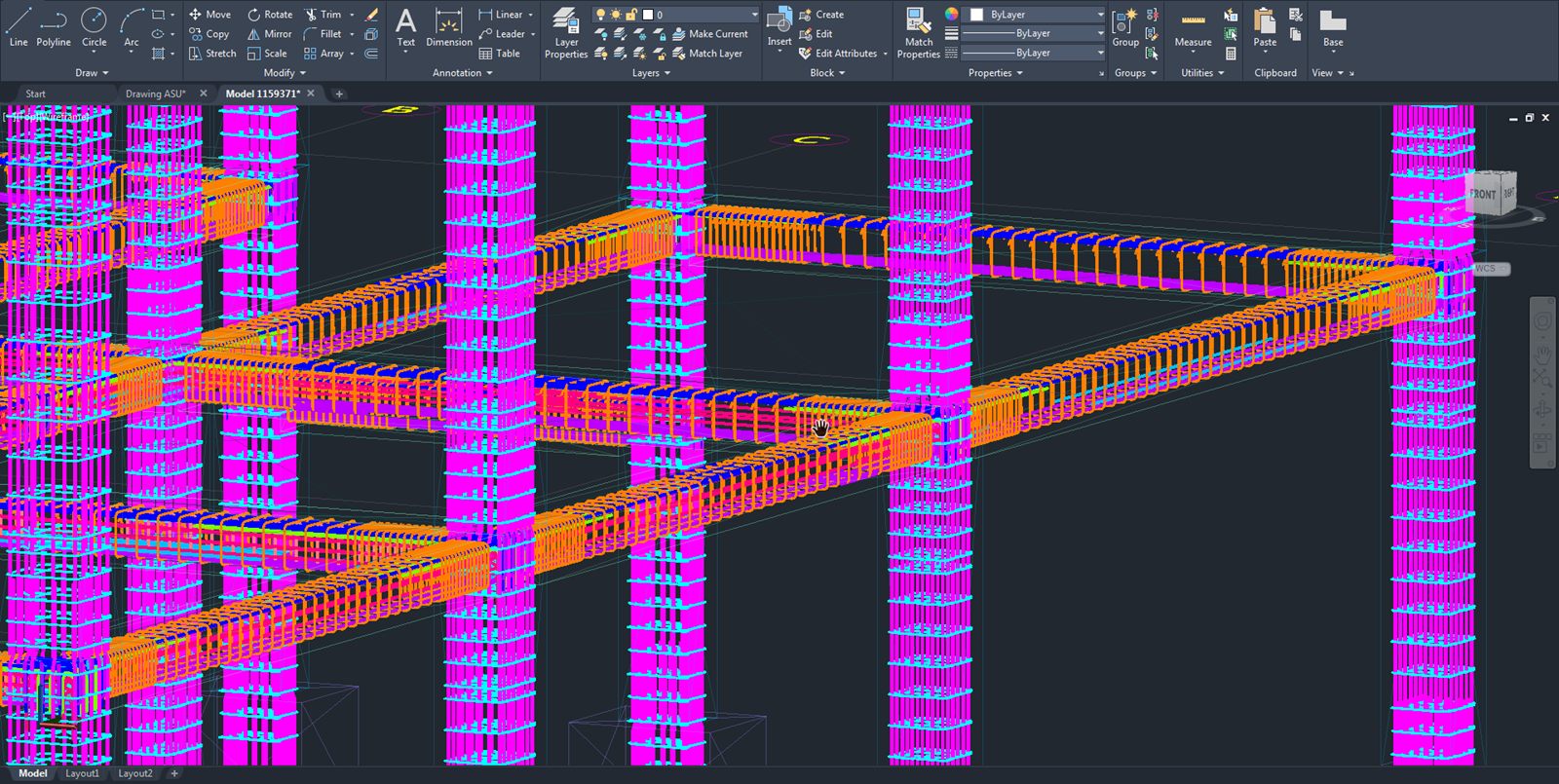
Not necessarily. A 3D environment improves visualization and coordination, while BIM depends on the wider project workflow, information requirements, exchange formats, and connected project systems.Can SIDA Concrete export AutoCAD drawings?
Yes. SIDA Concrete supports drawing exports in DWG and DXF formats and can generate block-based drawing outputs for AutoCAD workflows.Final Thoughts
Concrete detailing software is the bridge between reinforced concrete design and construction execution.It helps engineers turn approved design information into practical reinforcement drawings, coordinated schedules, clear cut-off data, and editable construction documentation.
For reinforced concrete beam and column projects, SIDA Concrete provides a 3D, model-based workflow for detailing, verification, bar schedules, cut-off tables, steel wastage reporting, and DWG/DXF outputs.
Explore SIDA Concrete to create clearer, more coordinated reinforced concrete drawing packages for your next project.
 Write a comment


